
Computer Aided Design & BIM
Customised AutoCAD since 1989, MultiSuite structural detailing, and a realistic view of what BIM does and does not deliver.
Computer Aided Design
David French Partnership went over to CAD back in 1989 with AutoCAD release 10 running on the DOS operating system. Our first CAD computers were a Dell 386 20MHz and a Dell 386 25MHz machine. Back in those days, to run AutoCAD, you had to buy a 'maths co-processor' chip to do the calculations. This cost £750 for the chip on its own. It is amazing how things have moved on with modern high-speed computers about half the cost of that maths co-processor.
From the outset David French Partnership planned to make our use of AutoCAD as efficient as possible and planned our approach carefully. We wanted to have a system that was uniform across the whole company so drawings produced from each technician all looked the same with uniform layering and styles. We recognised the advantages of being able to customise AutoCAD and our systems have always had time saving customisation. Our drawing template has many predefined layers, customised line types, hatch patterns and text styles.
One of the first problems we found with AutoCAD was that, in those days, there was no way to work with multiple scales on a drawing. We found this to be a big issue when producing engineering drawings and details. Looking through CAD magazines I came across an advert for 'MultiScale'. After trying a demonstration copy of the software we ordered it for all our systems. This enabled us to achieve exactly what we needed.
We were so pleased with 'MultiScale' that we asked the developers, 'Computer Draft Systems' (CDS) if they had any other utilities. Initially they were reluctant to talk about their software in development but eventually they admitted that they had a package 'MultiSteel' under development. We saw this software about 6 months before its planned release and we were so impressed that we immediately ordered it for all our systems and had a Beta copy installed a few months ahead of its release.
Initially there was only the steel package but we then persuaded CDS to develop a reinforced concrete detailing suite which they did, and called it 'MultiRebar'. With both packages, we gave the developers input on the system operation and offered suggestions for possible improvements.
We now run with the full MultiSuite software on all our workstations and the developers have allowed us access to some of their special routines which allow our customisation to work seamlessly with their system. As well as Beta testing their latest versions we are a reference site for them.
Architects and CAD
Not all architects have changed over to using CAD for their drawings and this is a real shame. We appreciate that some architects like the flair and artistic scope of hand drawn drawings for the planning stage, but we feel that a well-executed CAD drawing can be equally good or even better.
The advantage of CAD drawings is they are more accurate and the big benefit is they can be shared between the design team. If we are given a hand drawing and asked to do the engineering often we have to re-draw it, at least in part, to enable us to show the structure and detail it. This takes time and adds unnecessary cost to the project.
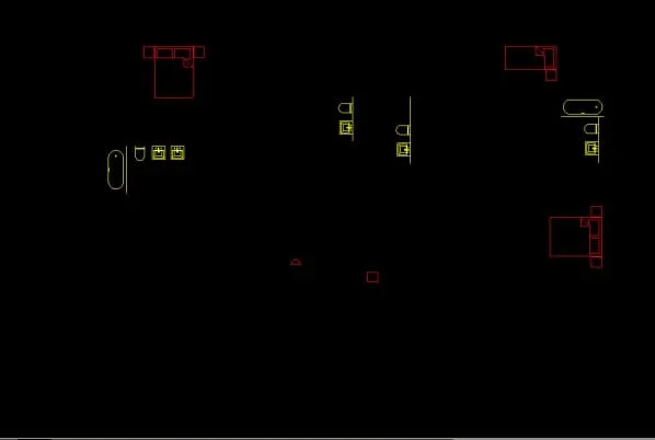
Even a nice CAD drawing can still leave us with a lot of work before we can use it. The drawing below was a drawing we received from an architect. On the face of it, it looks fine and achieves what the architect wants to achieve, looking acceptable when printed.
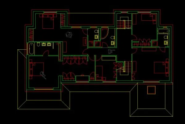
For us to use it we need to turn off the layers that we did not need for our structural work. The architect had neatly drawn furniture and even hanging clothes in the wardrobes. When we selected one of the coat-hangers and tried to turn off that layer we ended up with the drawing below.

When we investigated, it transpired that the architect had used very few layers, simply changing line colours and line types on one layer to produce his drawing. This is very poor practice. While it may achieve a drawing that is acceptable for him, and perhaps his client, it is useless to share amongst a design team.
What should happen is you have one line colour and one line type per layer. Different sections of the drawings should be on different layers so everything is easily identifiable and easily manipulated. British Standard BS1192 covers layering but as so often happens when bureaucrats get hold of things their layering convention is not intuitive.
Using this convention, the layer name for drawing a staircase should be:
A244_D02BD_ESTAIRS
This would be translated as the Architectural layer (A) showing spiral stairs (244_; using CI/Sfb), dimensions (D) on level 2 block B, zone D (02BD) with no status (_), at a detail equivalent to a 1:50 drawing (E). In more common applications, this layer name would often be shortened to A244_D using only the mandatory fields, or A244_DSTAIRS to help you understand the element type. How many of us know that element 244_ is a spiral staircase?
The logic behind a mandatory layering system is to enable drawings from different disciplines to be merged while each remains separate. For instance, using the example above A244_D is the layer for information by the Architect about the stairs whereas S244_D is the information by the Structural Engineer. Merging a drawing between the Architect and Engineer should provide 2 sets of information on 2 separate layers that will match if they are right.
We have a standard set of layers within David French Partnership which are matched to line colours and pen thicknesses in order to produce drawings to our satisfaction. Within our MultiSuite software we have the ability to convert our layer system to any other layer system if required. We also have tools to enable us to decipher Architects drawings that are poorly layered but this costs us time and money.
Anyone producing CAD drawings, please
- Use one colour per layerKeep layer colour set to ByLayer.
- Use one linetype per layerKeep linetype set to ByLayer.
- Use multiple layersSo the drawing can be easily used for other disciplines. For example, put furniture on a separate layer so it can be turned off.
- Avoid duplicate linesWe had one drawing where every line on the drawing was made up of 4 duplicate lines.
- Use sensible layer namesSo it is clear what you are drawing.
- Work accuratelyWe had a drawing recently where the roof pitch was called up at 42.5 degrees, but was actually drawn at 42.44553427 degrees. There were similar errors throughout and this meant problems with dimensioning. With modern CAD packages, it is easy to draw 100% accurately.
- Do not cheatIf you end up with a dimension that is not what you want, do not over-ride the dimension to make it what you expect. We had a drawing of a large building where a string of dimensions was out by almost 1000mm because an error in the setting out had been hidden rather than found.
The beauty of CAD is if you draw accurately you know if something will fit as the dimensions are 100% accurate.
One of the dictionary definitions of 'a team' is 'acting as a unit'. A design team on a building should work together and a key part of this is appreciating the needs of other members. Producing CAD drawings that can be easily manipulated by other team members is a key part of the design process, which is also the thinking behind our EASE early advice service.
Architects and BIM
Building information modeling (BIM) is defined as a process involving the generation and management of digital representations of physical and functional characteristics of places. Building information models are files, often but not always in proprietary formats and containing proprietary data, which can be extracted, exchanged or networked to support decision-making regarding a building or other built asset.
A BIM model is normally a 3-dimensional model and in the perfect situation allows all the disciplines to add their information to ensure that everything is correctly coordinated. In the ideal world, a change from one discipline can be reflected in all interlinked disciplines. For this to work efficiently the base computer model has to be accurate.
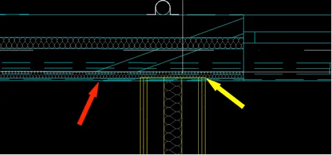
The drawing extract above is from a BIM model produced by an architect which achieved what he required, producing a 3D model of the multi-storey building that looked impressive.
When we came to use the model, we found that he had cheated, allowing walls to overlap rather than joining correctly. Once shaded and plotted this junction looked fine but when we came to add the structural beams we found it very hard to locate the correct intersection points for the beams. Also, the lines are not square, shown by a slight joggle in the lines. This means when you draw a beam perpendicular to the horizontal wall it is not parallel to the wall that you want to support. These errors are small but slow up the following disciplines design process.
The whole benefit of BIM is accuracy so each discipline can accurately position their information relative to others and if the base model is not accurate everything else that follows will have errors defeating the whole advantage of the approach.
The biggest problems with the BIM approach is time and money. The client has to be prepared to pay more for producing an accurate 3D model and to achieve this takes time. Most projects are on short design programmes and typically the engineering work has to start before the architectural design is complete and this cannot really be done with the BIM approach.
The costs of working on a 3D model are also much higher as in 2D it is fairly easy to show a beam but in 3D the beam has to be modelled and the connections detailed all in 3D. Although there are tools to enable this to be done for simple situations many architectural solutions require bespoke designs where the simple tools will not work.
At this stage, the 3D software is not as advanced as it needs to be and it is very hard to produce drawings to suit different disciplines. The software seems to be setup more for architects than engineers. Typically, engineers want to show the structure below a floor level whereas architects want to show the room layouts above a floor level and the software is not as flexible as needed to achieve this easily. At the moment, the 3D model is fine for the basic general arrangement drawings but it is still better to export to 2D for the detailed drawings such as reinforced concrete detailing.
David French Partnership LTD have Revit Software and are committed to BIM where the client is equally committed and prepared to fund the extra design and detailing costs with the intention of minimising issues during the build.
Get in touch
Sending us architectural drawings?
Well layered CAD saves everybody time and money. Call us before you issue and we will tell you exactly what we need.